Reflow soldering
Equipment
- Reflow soldering plate.
- Soldering iron with a conical tip.
- Magnifying glass.
- Isopropyl alcohol.
- Metal tweezers.
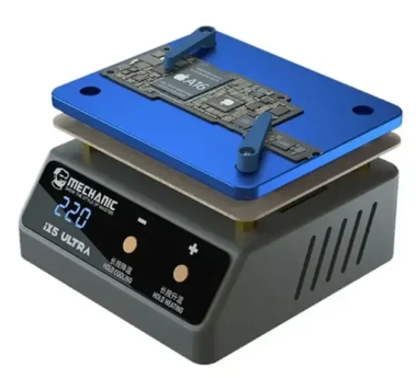
Image 23. Mechanic IX5 reflow heating plate
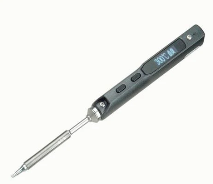
Image 24. TS-100 soldering iron
Reflow profile
- Set a target temperature on the Mechanic IX5 reflow plate.
- Activate the reflow process which will increase the temperate by 1°C each second until target temperature is reached.
- Once the reflow temperature is reached let it remain at this temperature until reflow has finished.
- Allow the PCB to cool which decrease temperature by 1°C each second until it is cool enough to handle.
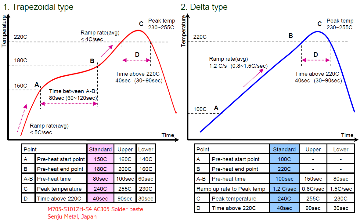
Figure 9. Different reflow profiles for lead free solder
(source)
The Mechanic IX5 can be used to follow an arbitrary reflow profile (including the shown trapezoidal or delta types). The delta type reflow profile is sufficient for the Oculink port.
Instructions
Reflow soldering components
- Apply stencil for Oculink connector and capacitors to spread solder paste.
- Visually check to make sure there are no bridges or missing solder paste on SMD pads.
- Place oculink port carefully onto SMD pads as to align them correctly.
- Follow reflow profile with a target temperature of 220°C and keep it there for 60 seconds before ramping it down.
- Visually confirm that there are no solder bridges on visible connections.
- Validate that there are no shorts or bad connections following electrical testing.
- Due to simple design of circuit the complications should only occur with the Oculink port itself.
- Here excessive or insufficient solder paste can result in short circuits or a missing electrical connection.
- Repeat steps 1 to 5 until the Oculink port is soldered correctly.
For the flexible PCB design continue to the following instructions below.
Soldering flex connector
This process is only required for the two part board which is connected over the flexible PCB.
- Perform reflow soldering of components for each of the two boards as described above.
- Tin the SMD connection pads on both the flexible PCB and M2 card and Oculink port board.
- Make sure that there is a minimal amount of solder to prevent shorts when reflow soldering connector.
- Check to see if amount of solder has same height across all pads. If there isn’t remove it until it is level.
- Focus on the Oculink port board first and preheat it to 140°C.
- Preheat the soldering iron with the conical tip to 280°C.
- Using metal tweezers carefully position the flexible connector to align with the SMD pads.
- Add flux to the flexible connector and board will help keep the connector in place once aligned.
- Do this under a magnifying glass with mechanical helper hands.
- Using the soldering iron solder the ground SMD pads after alignment.
- Be careful to not misalign the connector.
- Increase the preheating temperature of the board to 150°C or above if soldering isn’t occuring.
- Avoid preheating the board to too high of a temperature otherwise solder may become molten and components and Oculink port can be knocked off.
- Avoid keeping the board preheated for too long otherwise PCB will discolour.
- Make sure that you have soldered enough of the ground pads to keep the connector in place.
- Let the Oculink port board cool down and check that flexible PCB is mechanically secure enough to move assembly around.
- At this step there is no sound electrical connection between the board and flexible PCB.
- We only need it to be mechanically secure so we can perform the full reflow step under mechanical pressure.
- Place a weight on top of the flexible PCB connection to equally apply force on the SMD pads.
- The weight should cover the entire flexible PCB connection pads.
- The weight should not melt at the reflow temperature of 220°C.
- The weight should be secure and stationary during reflow process.
- Perform reflow soldering of the flexible PCB connection while the connections are under constant force.
- Since there are no spring contacts, the z-height tolerance of the connection is very low.
- To guarantee a good electrical connection the reflow process has to occur while the pads are under compressive pressure.
- Be careful not to disturb the existing connections such as the Oculink port and capacitors.
- Perform electrical tests as described in electrical testing.
- This is done to make sure shorts don’t occur due at the flexible PCB connection with the Oculink port board.
- If shorts do occur at this step repeat steps 1 to 10 with less solder on the pads.
- If these is a missing electrical connection make sure that sufficient pressure has been applied during reflow.
- Repeat setps 1 to 10 for the M.2 card.