Electrical testing
Single board validation
- Oculink port has a small pitch of 0.2mm which can easily create solder bridges.
- Validate this by connecting the Oculink port to the unpowered PCIe eGPU board.
- Refer to M.2 pinout and PCIe pinout for the electrical connections to test for.
- Depending on the design the PCIe lanes may be connected in opposite polarity and/or in opposite orders.
- Check for short circuits and bad connections.
- Use a magnifying glass to position multimeter probes onto the exposed electrical contacts.
Flexible PCB multi board design
Validation of flexible PCB design will be done in three passes.
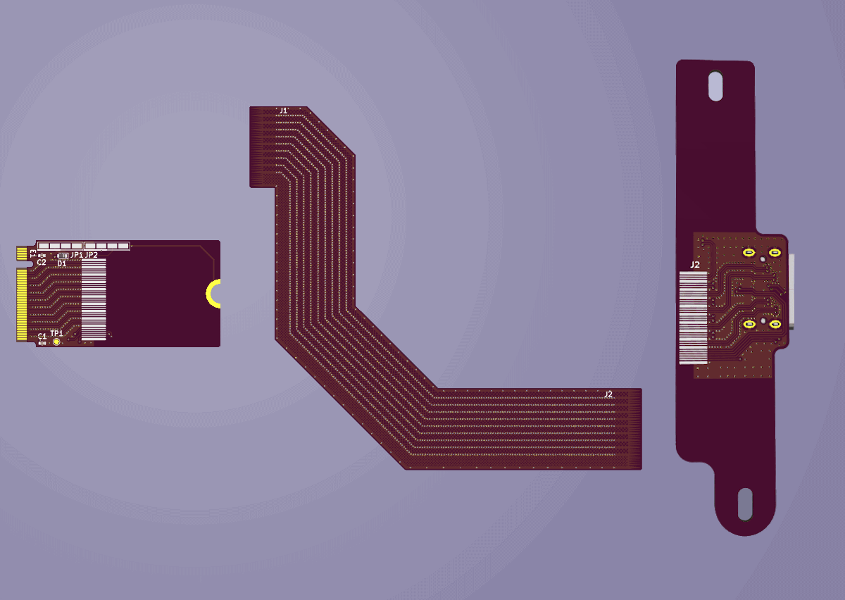
Image 12. Custom M.2 to Oculink adapter with flex connector 3D renders
1. Oculink port board
- After Oculink port has been soldered to PCB perform similar checks as with the single board design.
- Instead of using the M.2 connection use the exposed flexible PCB SMD pads to test for shorts or bad electrical connections.
2. Flexible PCB to Oculink port
- After soldering flexible PCB to Oculink port board perform the same check but with the exposed flexible PCB pads on the M.2 side of the flexible PCB.
- Perform visual checks of the flexible PCB at the soldered connection. Since the polyimide is translucent it is possible to detect solder bridges.
- If there are any shorts or bad connections they are likely isolated to the flexible PCB connection since we have already verified the Oculink port itself.
3. Flexible PCB to M.2 port
- After soldering flexible PCB to M.2 card perform same check as with the single board design.
- Perform visual checks of the flexible PCB at the soldered connection. Since the polyimide is translucent it is possible to detect solder bridges.
- If there are any shorts or bad connections they are likely isolated to the flexible PCB connection on the M.2 card side.
- Due to steps 1 and 2 the Oculink port and flexible PCB connection on the Oculink board side are verified.