Structures
PCIe receive and transmit lanes and reference clock are high frequency differential signals. There are many possible designs for a differential transmission line.
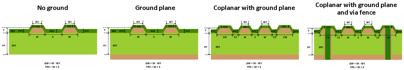
Diagram 3. Differential pair topologies
(source)
Common mode noise
In theory a perfectly balanced differential pair would only need two conductors to handle the symmetrical current path however this should not be relied upon.
- Common mode noise can arise due to power supply differences between host and device. This is especially important because we have a laptop powered by a USB C dock and an eGPU powered by a separate power supply.
- Without a ground plane or coplanar ground trace the return current for the common mode signal may be over a large loop area.
- This can pickup interference from environmental sources and harm signal integrity.
- Increases amount of EMI induced in signal traces within that loop area.
Crosstalk
Given our tight routing requirements our PCIe lanes would be extremely close together by only a few multiples of the trace width. This means we need to be very careful about inter-lane crosstalk.
- Can be fixed by increasing separation between lanes which is not possible given our tight space requirements.
- Adding a ground plane to confine the electric field generated by the differential pair (almost always helps).
- Adding coplanar guard traces to separate adjacent lanes and add additional E-field confinement.
- Sometimes can worsen crosstalk if guard trace is high impedance and functions closer to a resonant tank than a ground trace.
- Can be improved by turning coplanar guard traces into a via fence by stitching them to a ground plane
- This guarantees coplanar guard trace is low impedance.
- Also adds additional grounding with vias which further improves E-field confinement and prevents inter-lane crosstalk.
Best design
The following should be used for an optimal differential pair transmission line:
- Solid ground plane
- Coplanar guard traces
- Via fence
Through this we should be able to reduce crosstalk, handle common mode noise, and reduce EMI emissions even with tightly packed PCIe lanes.