Taper
Simulation setup
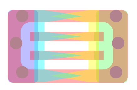
Image 21. Automatically generated taper ground plane for openEMS simulation
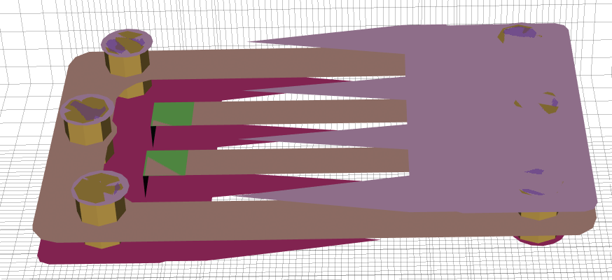
Image 22. Automatically generated taper ground plane 3D model
- Various geometries were auto-generated by a Python script which produced image files with different hatch configurations.
- These were then given to gerber2ems to simulate using openEMS.
- A parametric search over the width, length and overlap amount for the optimum search was performed.
- The overlap was a percentage of the length of the taper. E.g.
[0.5, 1.0, 1.5].
Parameter search
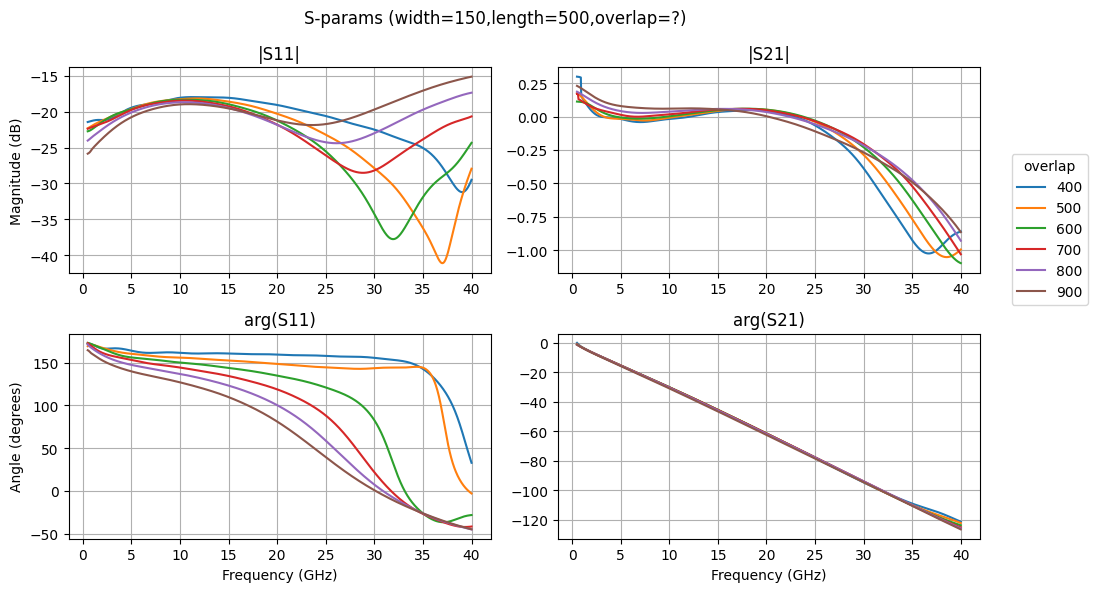
Figure 6. S-parameter results of parameterised search of taper ground plane with a hatch width of 150um

Figure 5. Reflectance results of parameterised search of taper ground plane with a hatch width of 150um
- The configuration with the lowest mean energy loss in our frequency range of interest (0GHz to 40GHz) was chosen.
- This was repeated for fixed width and length parameters, then for fixed width paramters, after which the optimum was then chosen.
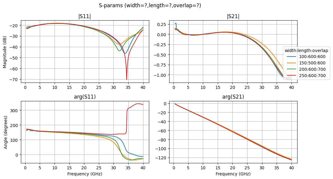
Figure 8. S-parameter results of parameterised search of taper ground plane across all parameters
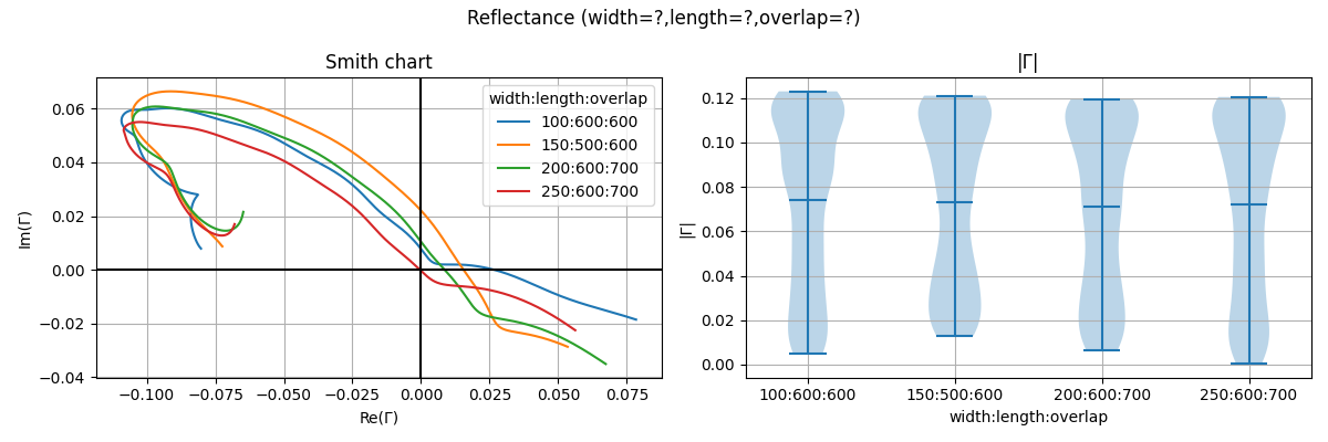
Figure 7. Reflectance results of parameterised search of taper ground plane across all parameters
Discussion
- Doesn’t simulate dielectric loss or skin effect which is important for predicting how lossy the design is, especially at higher frequencies where these effects are significant.
- Right now the gerber2ems script uses a perfect conductor as the metal material, however openEMS has ConductingSheet which simulates conductivity for lossy conductors.
- Limited resolution of the openEMS simulation meant that the infinitely pointy taper could not be simulated. This probably resulted in inaccurate simulated performance at higher frequencies.
Limitations
- This taper is supposed to be used to transition from the transmission line on the FR4 PCB to the flexible polyimide PCB.
- The thickness of the copper layer would need to be considered, however due to bugs in the gerber2ems simulation setup it is difficult to guarantee stable/correct results when connecting the micro stripline simulation port to a 3D metal mesh.
- An accurate simulation would require adding in the FR4 stackup and polyimide stackup including the solder bridge connecting the two PCB together. This would require gerber2ems to support much more complicated stackups.
- A hatched ground plane would need to be added to simulate how the taper behaves with a hatched ground plane.