Exporting PCB
Exporting PCB
Required files
These following files should be exported from your PCB design. This should be achievable from any PCB design software.
Gerber files (*.gbr)
- Specified geometry for copper layers is added to simulation (*_Cu.gbr).
- Edge cuts must be supplied (Edge_Cuts.gbr).
- Must be referenced to drill/place file origin.
- Uses the
4.6, unit mmcoordinate format.
Drill files (*.drl)
- Only plated through holes such as vias are added to simulation (PTH.drl).
- Must be referenced to dill/place file origin.
- Uses decimal format in millimeters.
- Excellon file format in alternate drill mode.
Ports file (*-pos.csv)
- Only specially marked simulation ports are imported into simulation.
- Reference must be “SP{number}”.
- Value must be “Simulation_Port”.
- xy position:
- Must be in millimeters.
- Referenced to drill/place file origin.
- Only rotations of
[0, 90, 180, 270]are allowed. - File must be in
csvformat where first row is the header. - Order of values is given in the following table.
| Ref | Val | Package | PosX | PosY | Rot | Side |
|---|---|---|---|---|---|---|
| SP0 | Simulation_Port | * | 0.4 | 2.5 | * | |
| SP1 | Simulation_Port | * | 0.6 | 2.5 | * |
Exporting from KiCAD 8.0
Creating simulation ports
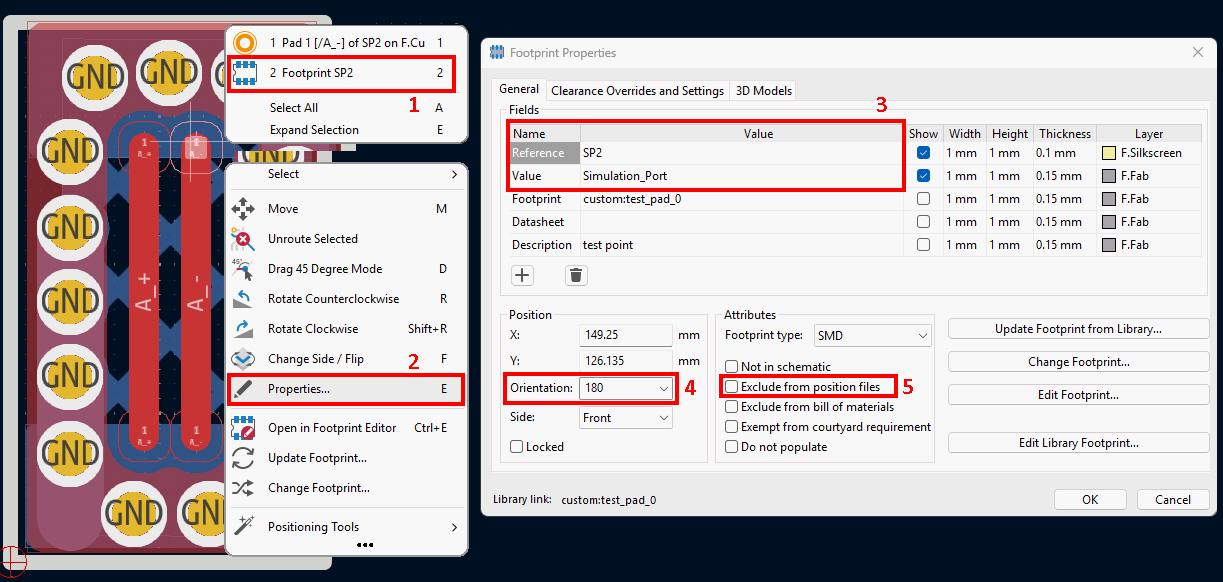
Figure 5. KiCAD 8.0 simulation port properties
Check to see if a component on the board is setup correctly to be imported as a simulation port into openEMS.
- Select a footprint.
- Select properties.
- Check to see if the
ReferenceandValueare set toSP{number}andSimulation_Portrespectively.- This should be done in the KiCAD schematic file by editing the properties on the component.
- You can create a library of simulation port cusotm footprints in KiCAD or reuse an inbuilt footprint.
- Change orientation if port is the orientation after being imported.
- Make sure that it is not excluded from the exported position files.
Begin exporting files
Use the following menu to export each of the required file types.
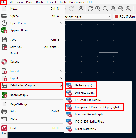
Figure 1. KiCAD 8.0 file menu options for exporting design
Export Gerber files
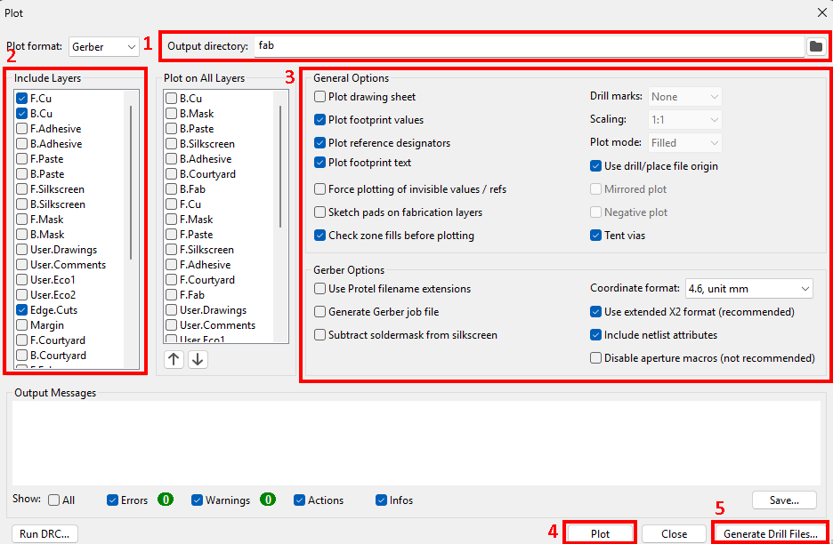
Figure 2. KiCAD 8.0 export Gerber files dialog
- Select
File > Fabrication Outputs > Gerbers (.gbr).... - Choose output folder.
- Include layers that you want to export.
- Setup options.
- Press
Plotto export gerber files to output folder.
Export drill files
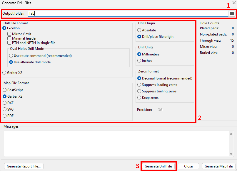
Figure 3. KiCAD 8.0 generate drill files dialog
- Select
Generate Drill Files...from previousGerber filesdialog box. - Choose output folder.
- Setup options.
- Press
Generate Drill Fileto export drill files to output folder.
Export ports file
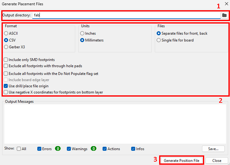
Figure 4. KiCAD 8.0 generate placement files dialog
- Select
File > Fabrication Outputs > Component Placement (.pos, .gbr).... - Choose output folder.
- Setup options.
- Press
Generate Position Fileto export ports to output folder.